

Water Level Controller Installation Examples
Rugged Construction Enables Installation with Excavators
The heavy-duty metal construction and robust pipe connection makes it possible to assemble our products on the side of the ditch before placing them. Aluminum in-line assemblies are easy to place manually. An excavator can be used to place the larger flashboard products.


Backfilling With an Excavator is Acceptable
Go slow and carefully place loose soil to secure the pipe then backfill the box. A mini is recommended because it is easier to control.
Use caution when backfilling single-sided flashboard risers. The boxes can be pushed forward and the support frames can be bent if dirt is applied too quickly.
Nothing is indestructible but our 6-inch aluminum inline structures will take a beating with no damage. The flexible coupling and pipe are the most delicate aspects of the system.
The stoplogs do not need to be installed before backfilling.
Clearly an excavator can easily smash a box or snap the pipe so careful operation is important.


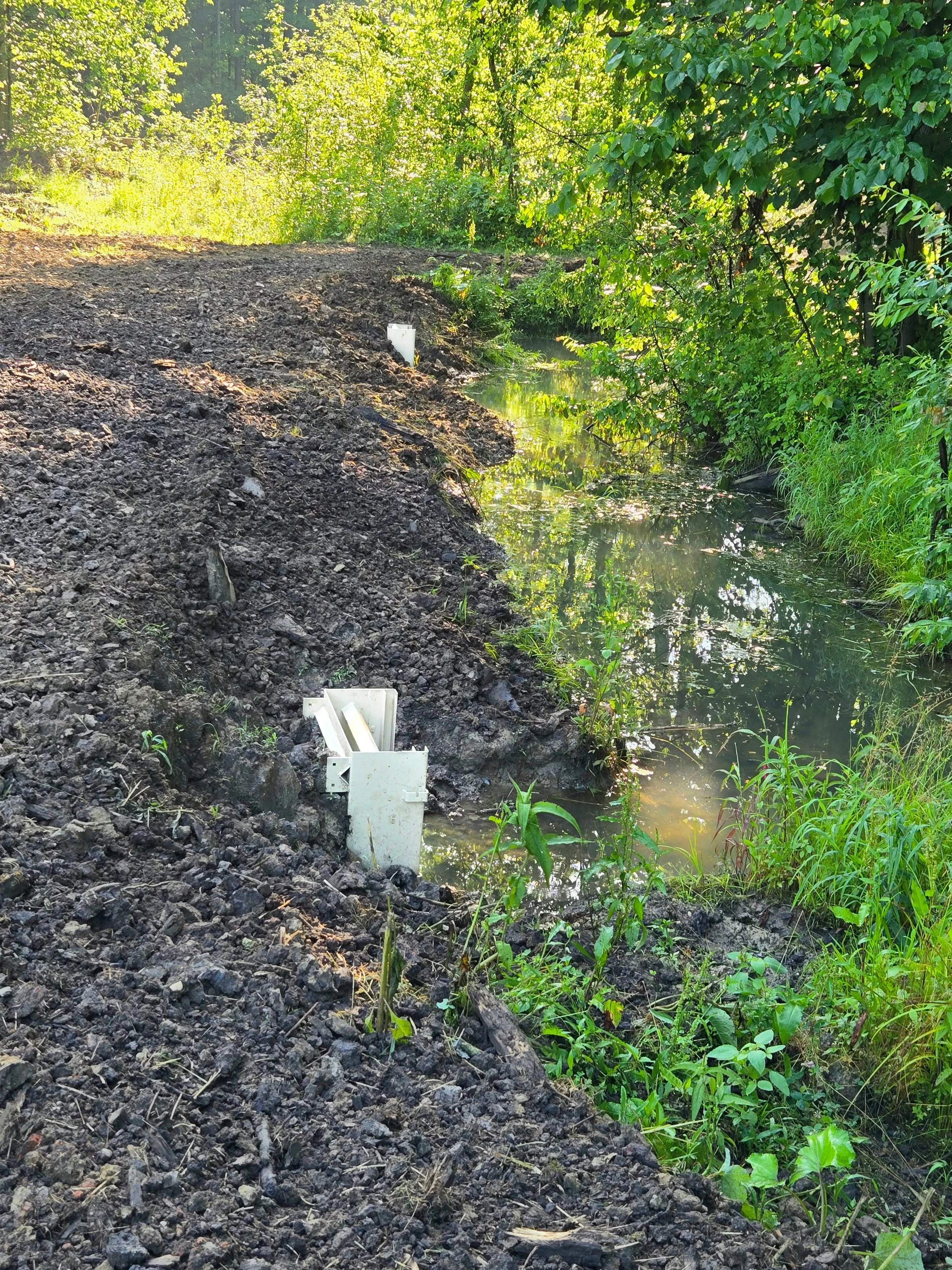
Risers can be set on the ends of an existing pipe
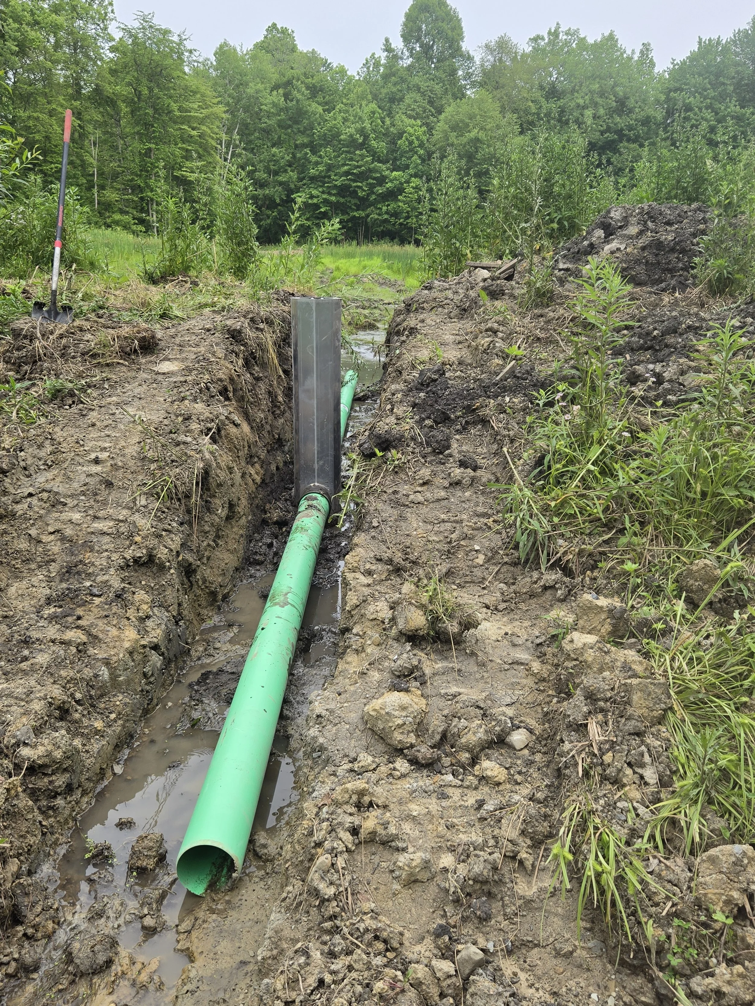
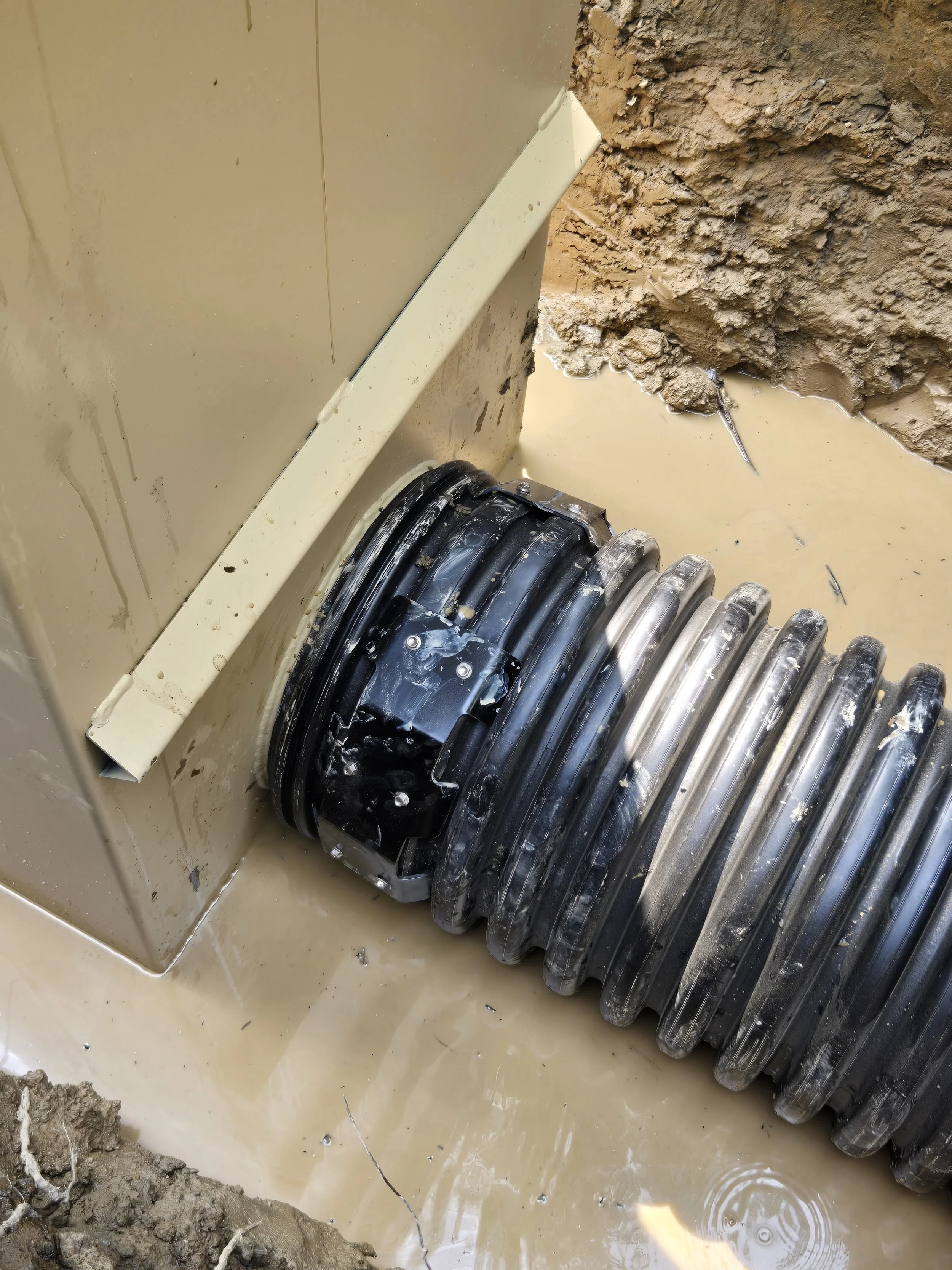
A new pipe and riser was installed to draw water from this distribution ditch. This new riser is being added to an existing pipe so the water flow can be split and/or switched between pipes.
Carefully and Slowly expose the pipe and level the space below the bottom of the pipe to roughly match up with the stub on the box. A good operator can do this with an excavator but it is best finished with a shovel.
Do not dig too deeply because the box needs firm ground under it.
If the pipe end is damaged, it may need to be sawed off to present a clean end. In this example, the pipe was uncovered in good condition.
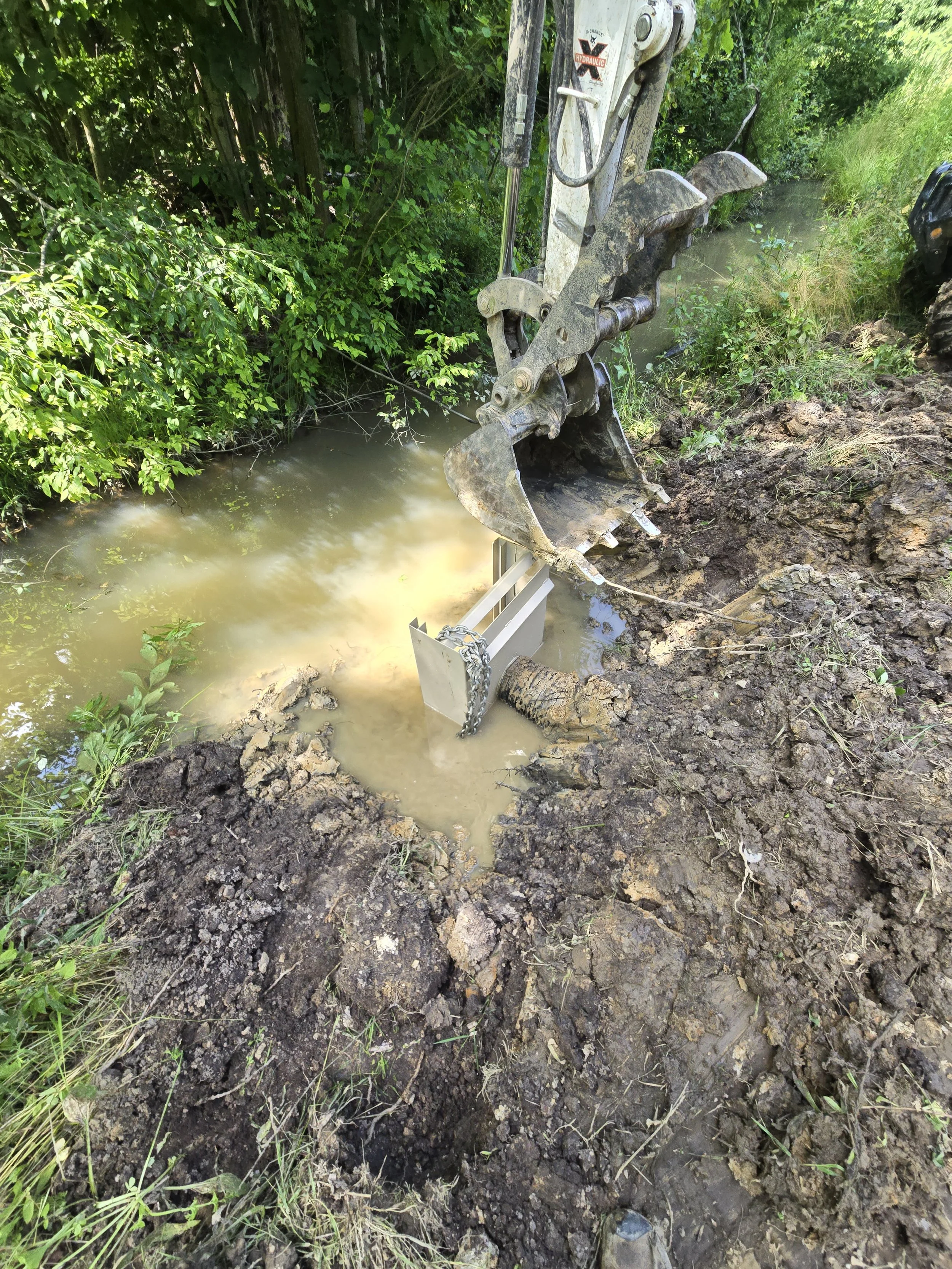
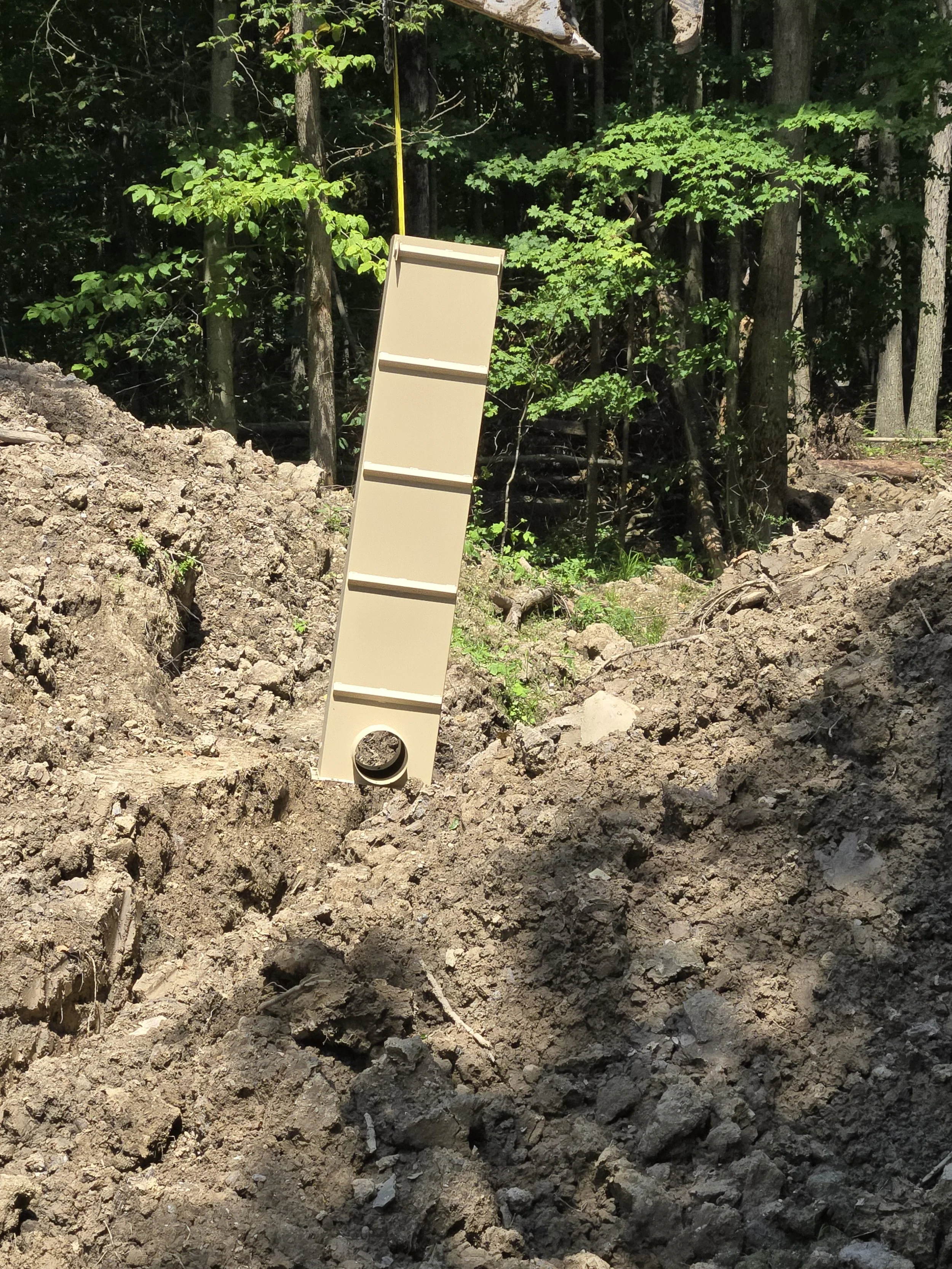
Lift the box in place manually or with the excavator.
Wrestle the box into place to get the riser stub inside the pipe. Use a shovel and/or the excavator the gently push the box into place.
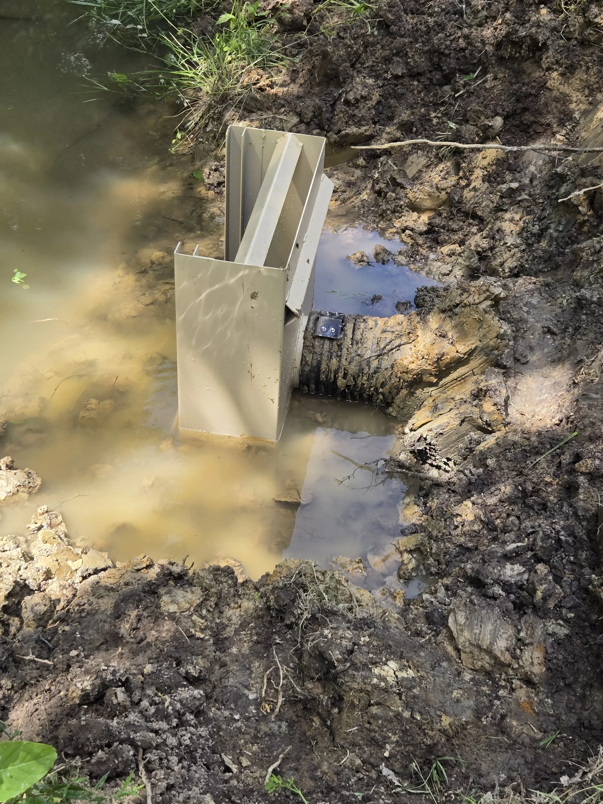
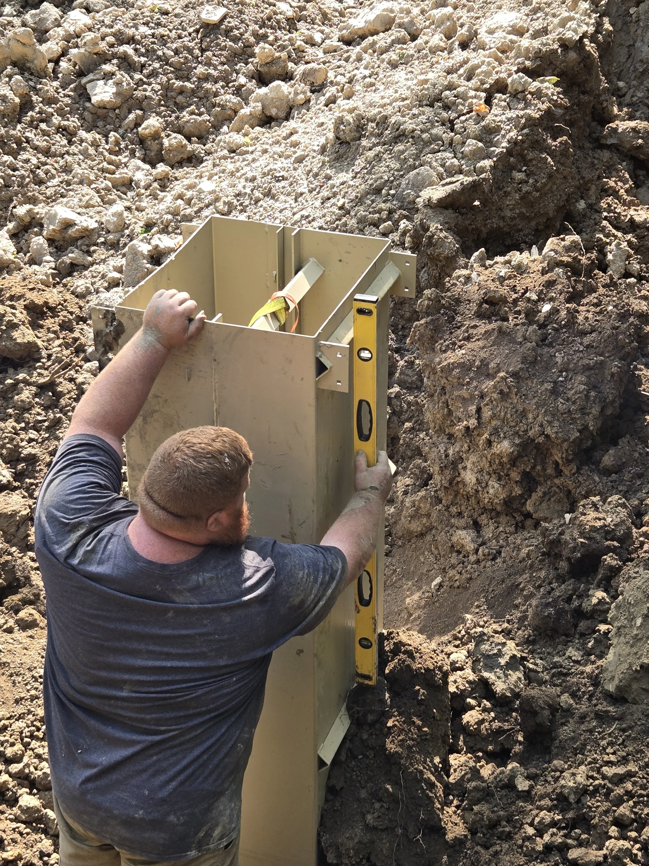
Use the excavator and some elbow grease to square up the box into a plumb and level condition. The box is sturdy enough to withstand gentle downward pressure from the excavator to tamp it into place.
If desired, drive rebar pins in the box to secure it. These are not needed if the preparation is good and the box is on a secure footing.
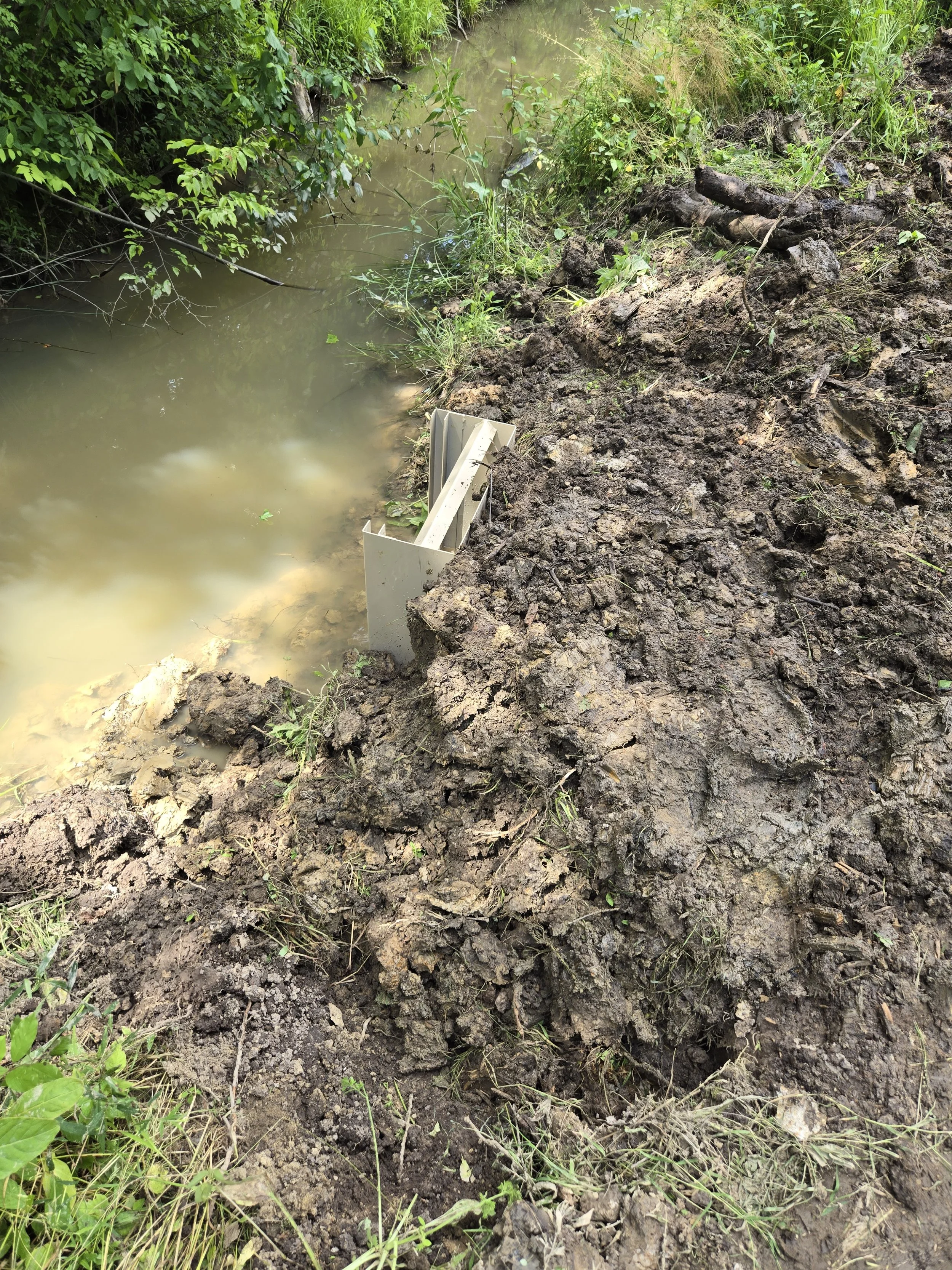
Attach a cleat to hold the pipe and box together. This is important.
Backfill
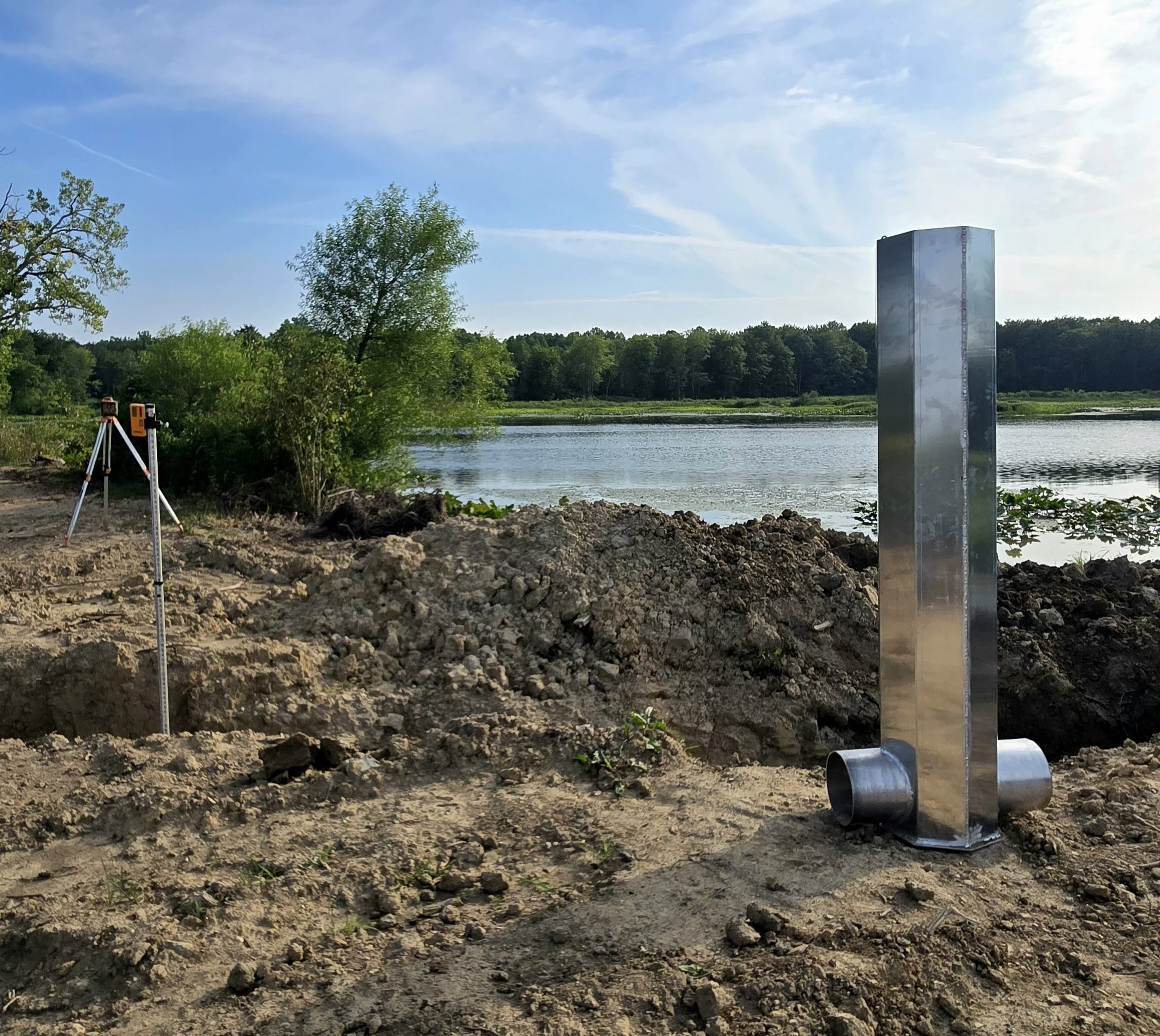
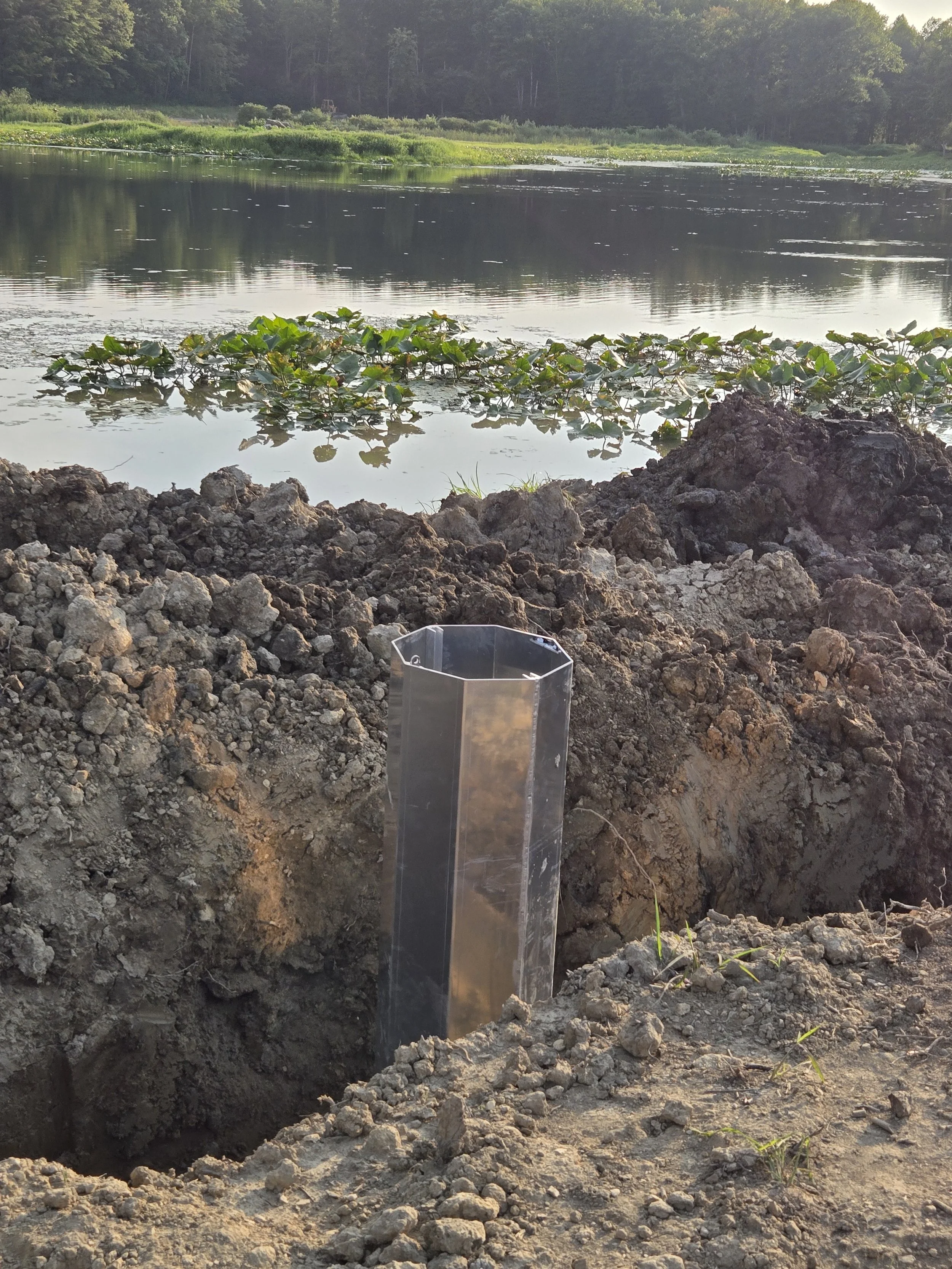
Installing a Large Steel Inline Water Level Controller
This project installed a 12-inch x 10-foot steel inline water level control box into the dam for a new 0.8-acre pond. The base of the dam is 60 feet wide and the top is 20 feet wide. The maximum depth of the pond is 8 feet at the drain. The spillway is at the other end of the pond drains into a large meadow. It is 20 feet wide and is set at 8 feet above the drain. The dam rises another foot above the top of the inline structure. This provides a 3-foot buffer for flood water before the dam might breach. The area below the dam is a 5-acre wetland buffer for a 20-acre lake (all on the same property).
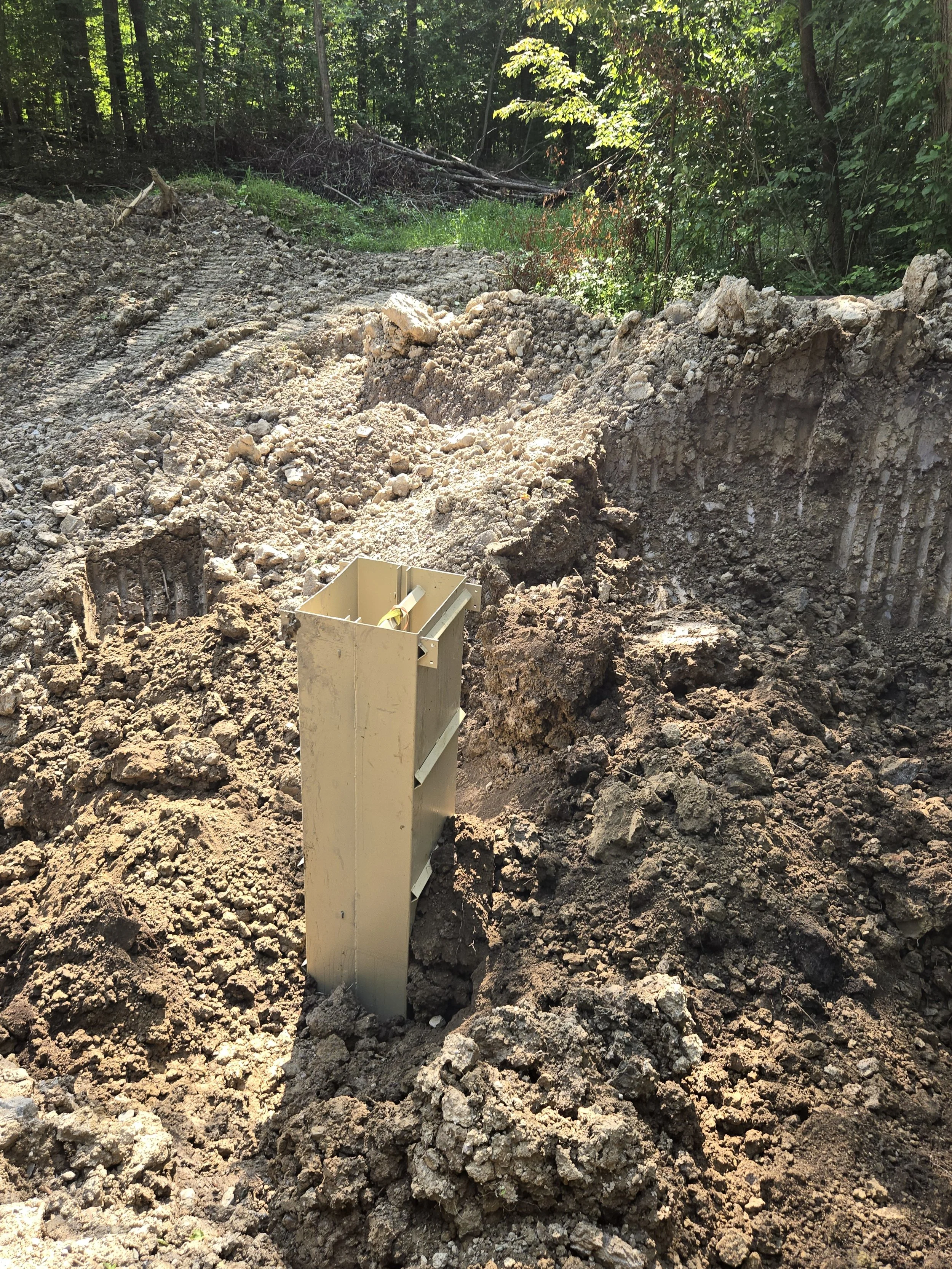
Moving a large steel inline water level controller into place in a ditch dug though a new dam. This structure weights 565 pounds and must be craned into place. Our aluminum DrainBox of the same size only 180 pounds and can be manually placed.

Inline DrainBox is in the ditch and roughly positioned.
Notice the dirt is pulled back from the sides of the ditch to provide a safe working environment.
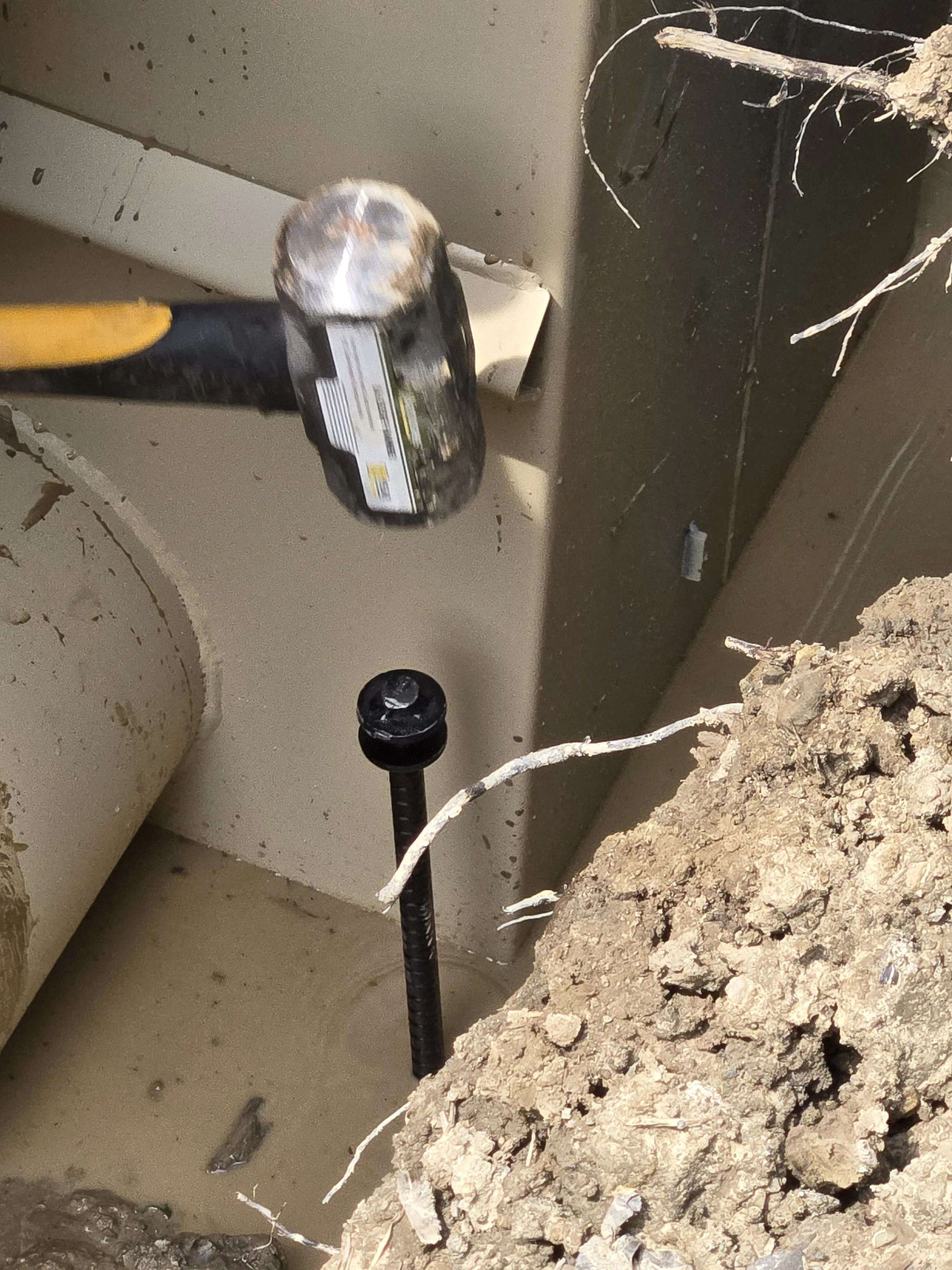
Pegging the four corners in place with 36-inch 5/8 rebar pegs.
This is essential on large boxes to get them square and to prevent them from falling over when working to attach the pipes.
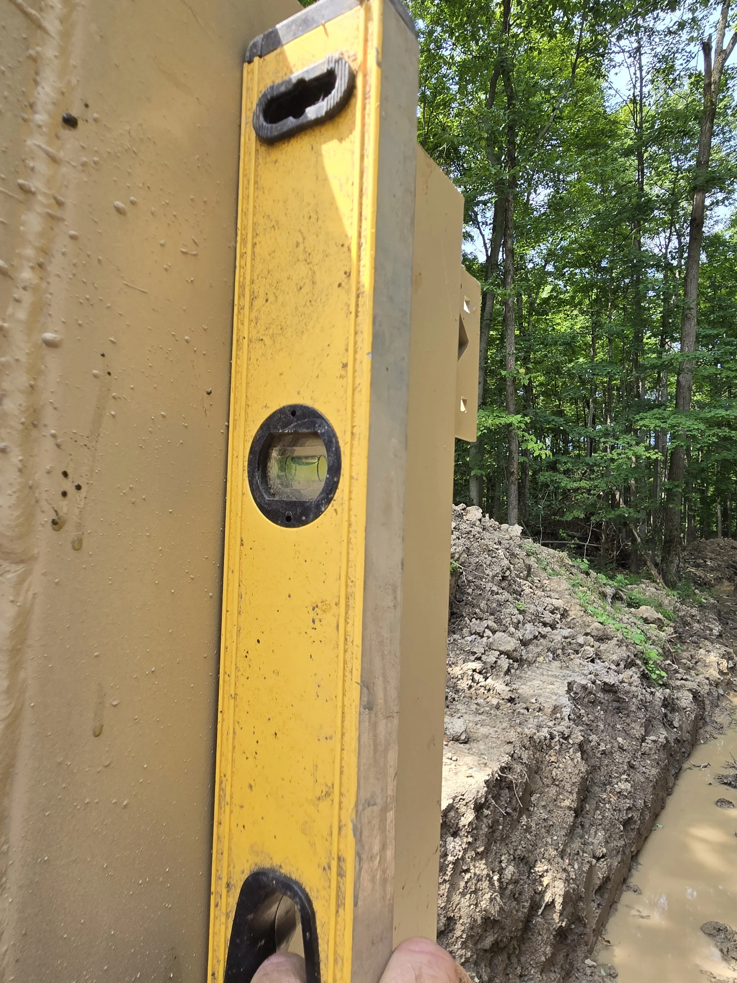
Adjust the pegs to ensure the box is plumb in both directions. Pound the pegs further into the ground on the side that will pull the box into the plumb position.
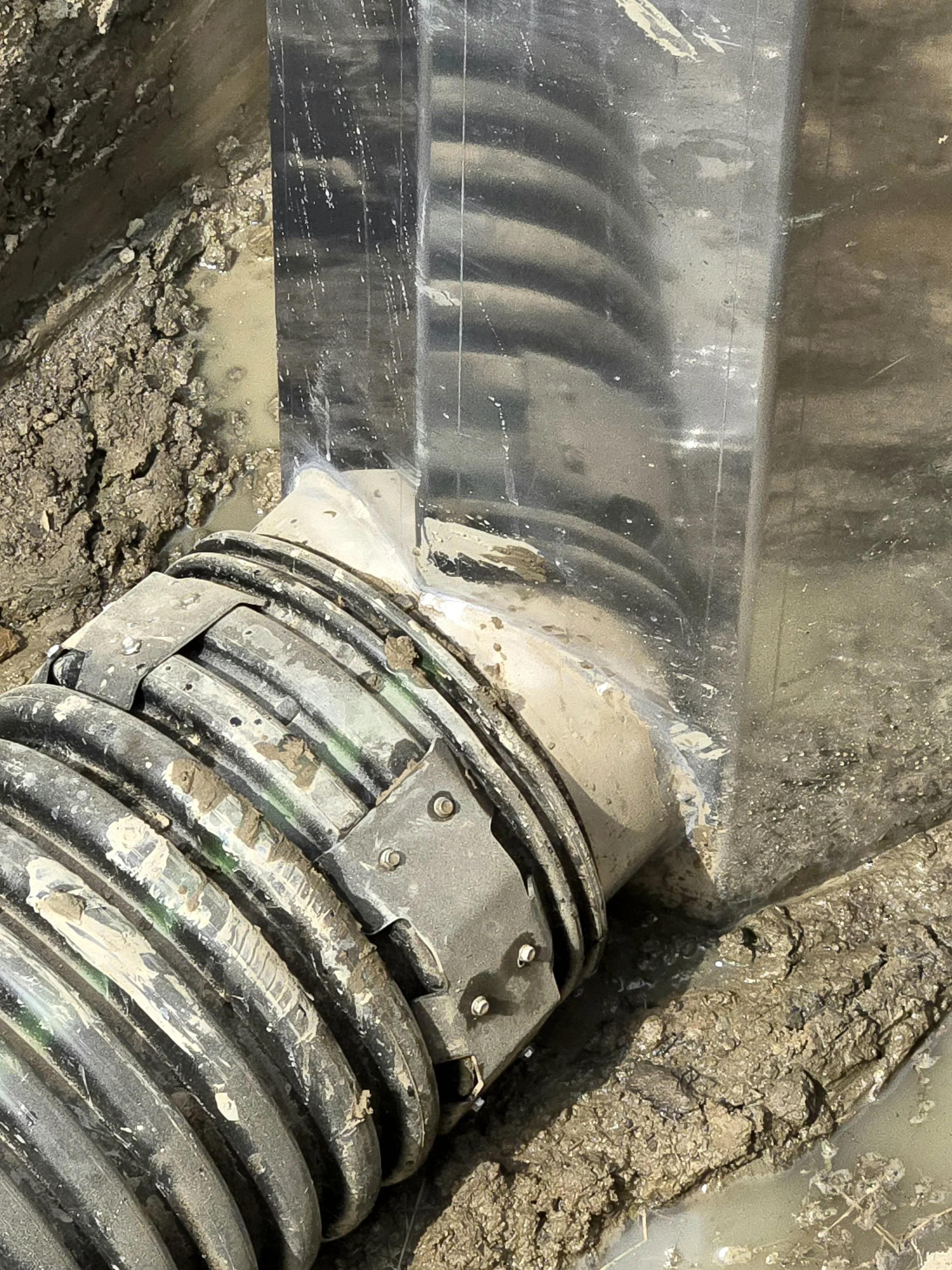
Install the outlet pipe and fasten it in place with cleats and self-drilling screws.
Place the compression clamp(s) on the pipe outside of the ditch to make it easier to install. Snug the clamp to the pipe but do not tighten the clamp sufficiently to compress the pipe.
This pipe was sawed off to remove the mating end.
Push the inlet pipe into place and EVENLY tighten the compression clamp(s).
Slowly start backfilling and periodically check that the structure is plumb.
CAREFULLY and strategically apply dirt to nudge the box to keep it plumb.
This installation used a 25 ton excavator for this job.
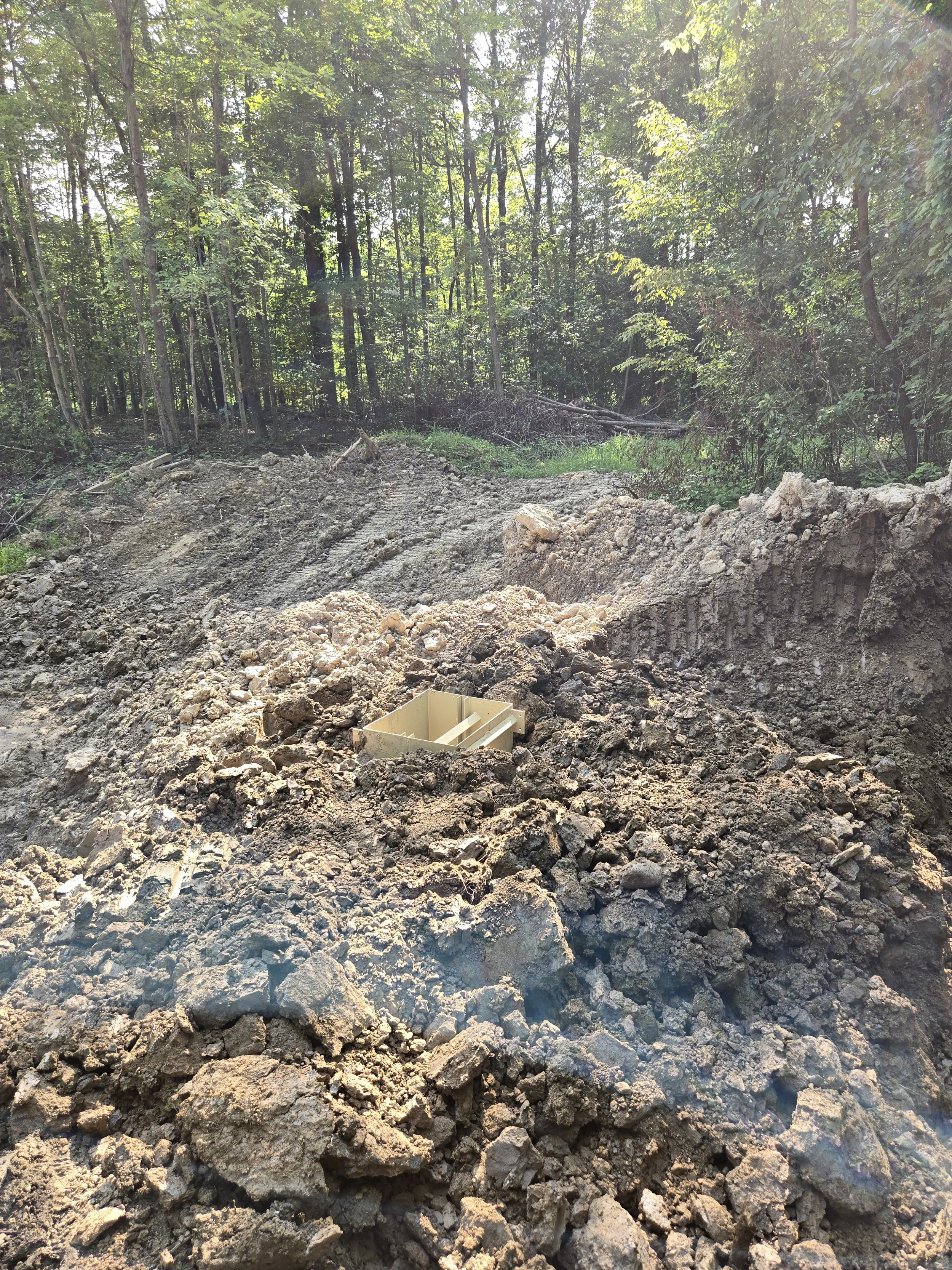
Finished Backfilling.
Allow the dirt to naturally settle.
Use a small machine to groom the area.
Installing a Large Inline Aluminum Lake Drain
This project added a 12-inch X 8-foot drain to an existing 15-acre lake. The lake has a separate spillway with a one-foot flashboard to trim the water level. This new inline drain is intended to enable winter drawdown to manage the weeds and lilies that are beginning to choke the shallow portions of the lake. A 12-inch pipe would be insufficient for a lake of this size but it will be very effective at slowing managing the water levels for maintenance and winter drawdown.
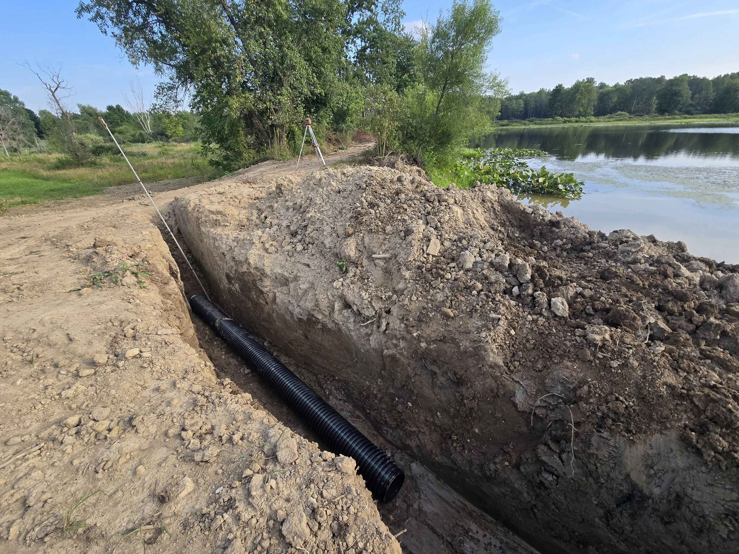
A 200-foot ditch was prepared and laid with 12-inch drain tile. The tile goes across the dam and through the meadow to the ditch where the lake normally drains.
The lake was lowered as much as possible and dirt was pushed into the lake to form a working area to install the new drain.
The ditch is prepared to receive the aluminum DrainBox. The dirt was pulled back to avoid the risk of working inside of deep ditch.
Use safe excavation practices. Deep and steep holes are very dangerous!
The DrainBox is set in place manually. It weighs about 150 pounds which is a big advantage over a steel box.
The DrainBox outlet is slid into the outlet pipe and fastened securely with the supplied cleats.
The gasket end of the pipe was left in place. It can be sawed off for a tighter fit.
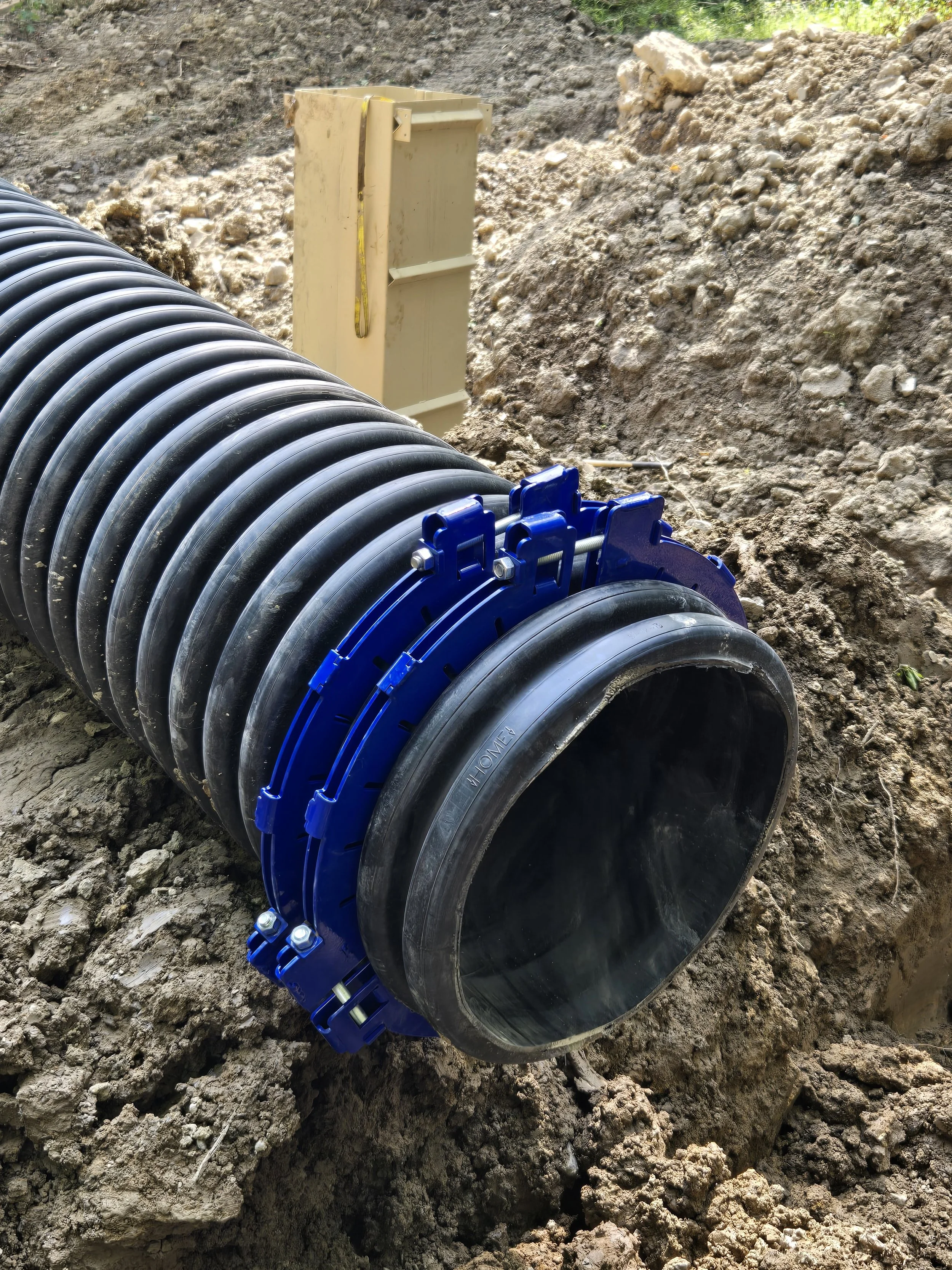
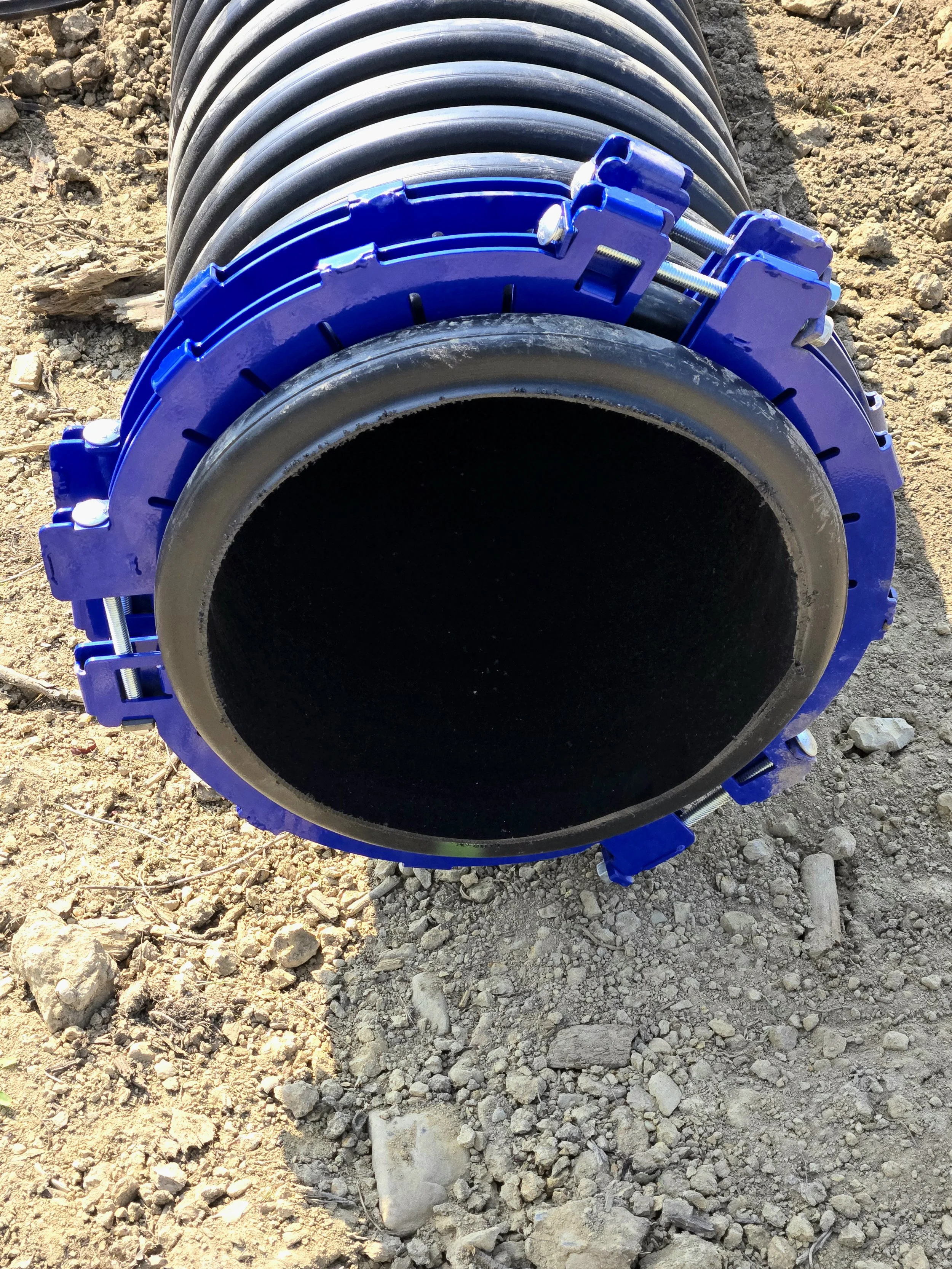
Compression clamps are fitted to the outlet pipe before it is placed in the ditch.
The clamps are indexed by one-half of a tooth to equalize clamping forces.
The end of the pipe was sawed off to ensure a good fit.
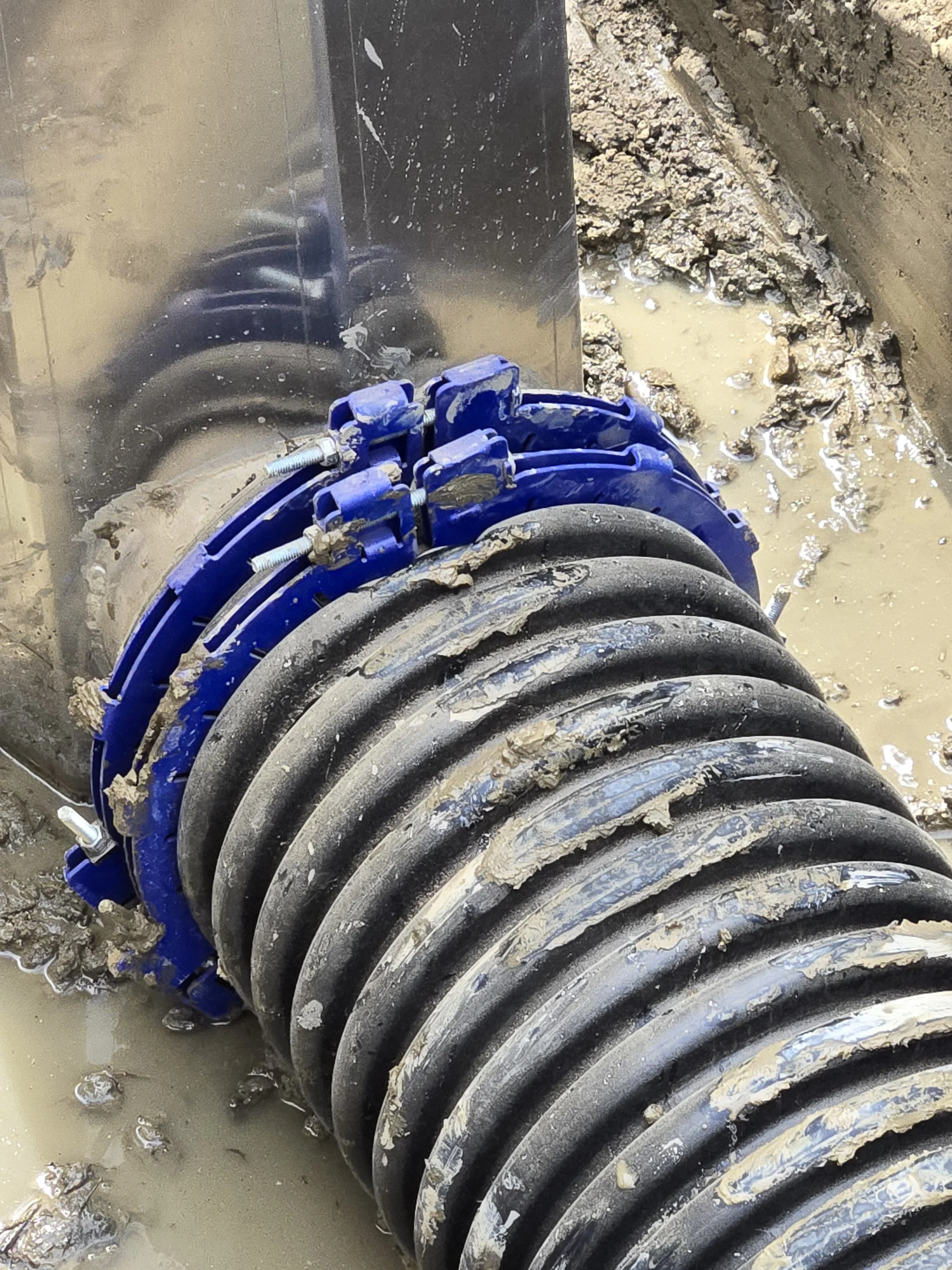
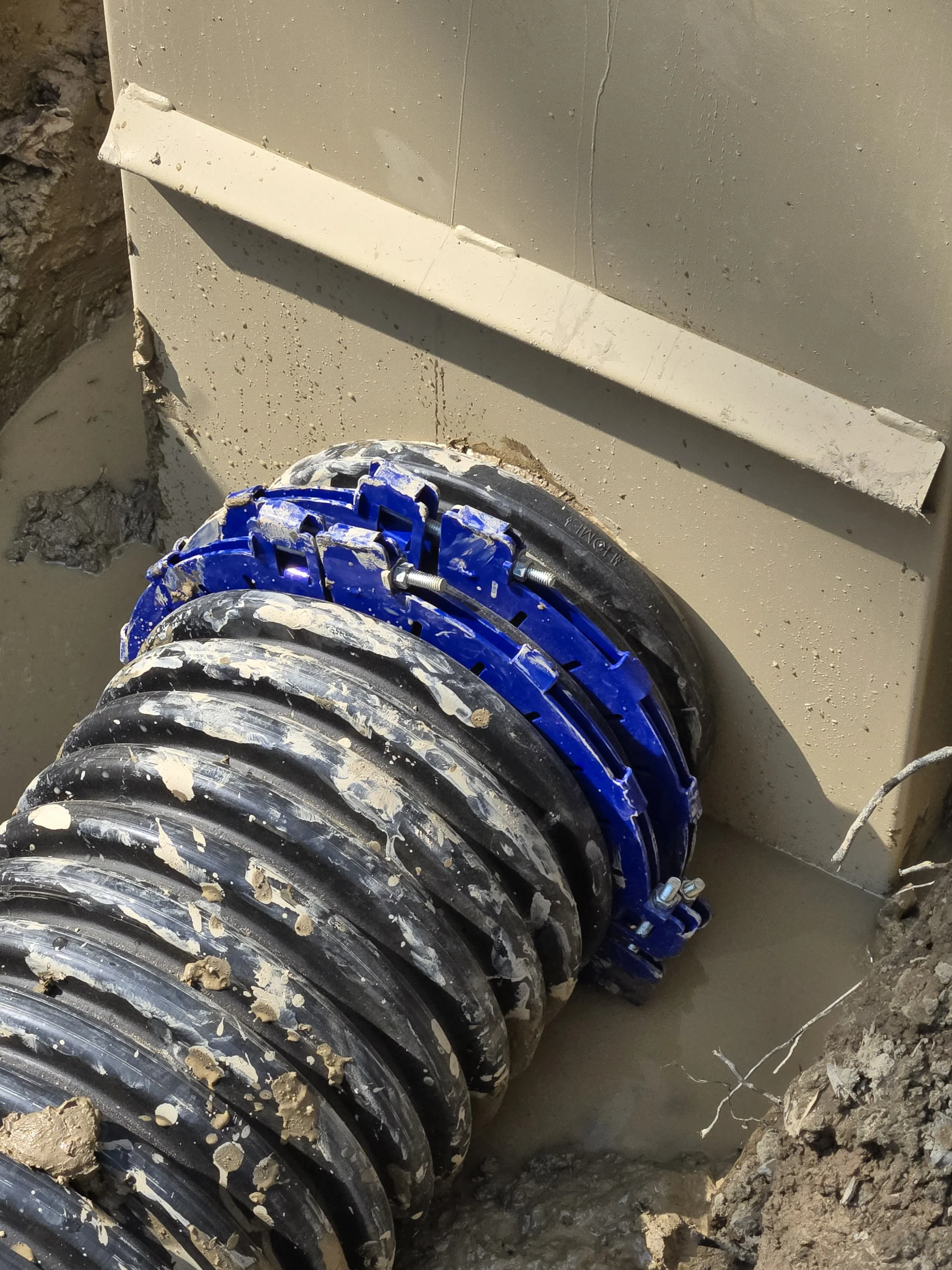
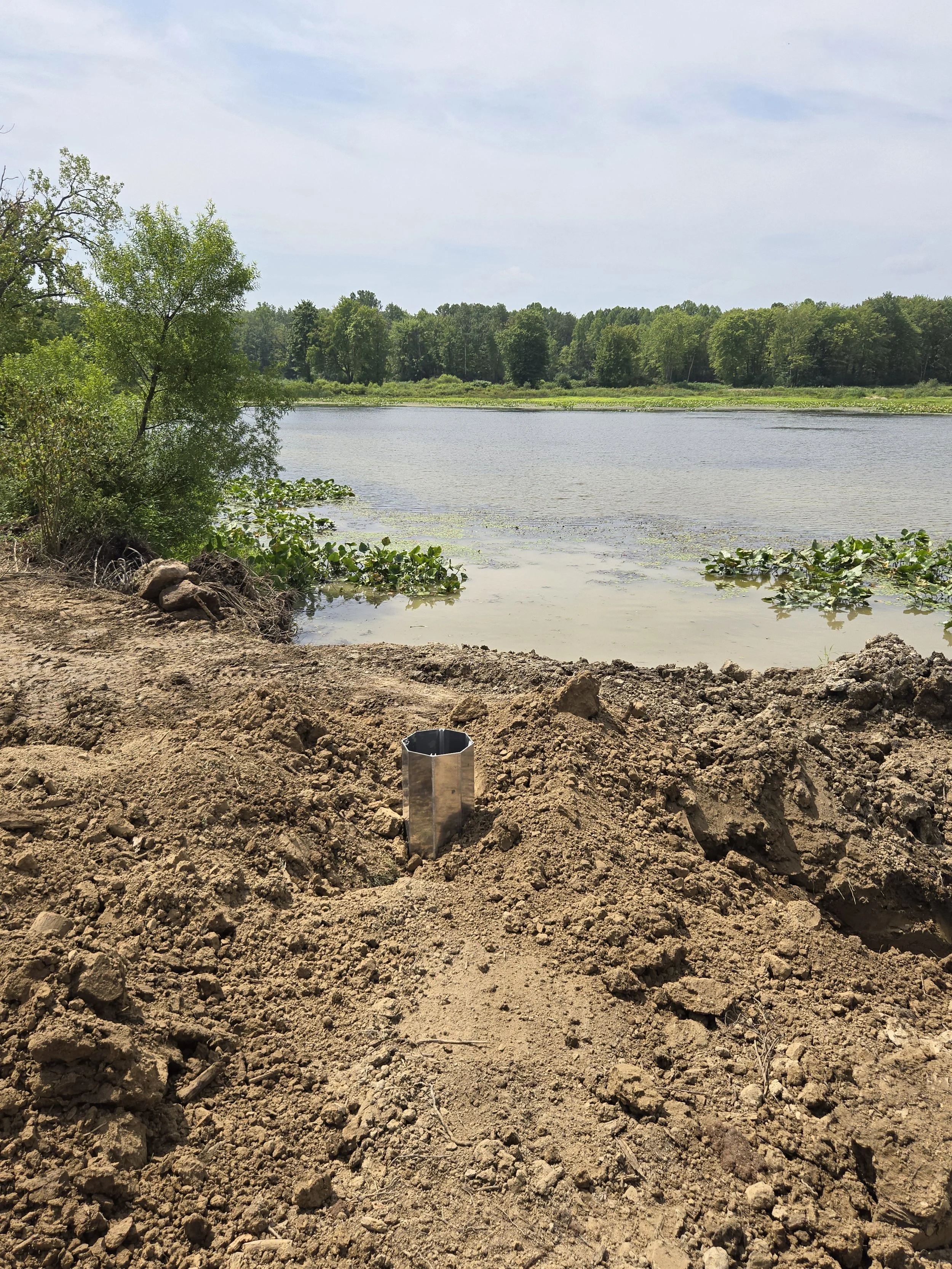
The pipe is slipped over the inlet stub on the drainbox.
The compression clamps are tightened EVENLY.

Loose dirt was strategically placed over the pipe and against the box to get the box plumb and level.
A front end loader was used to backfill this box because the dirt was being transported from another area.
The box and pipe were backfilled with the loader.
No particular care was taken other than to avoid placing stones in the backfilled dirt.
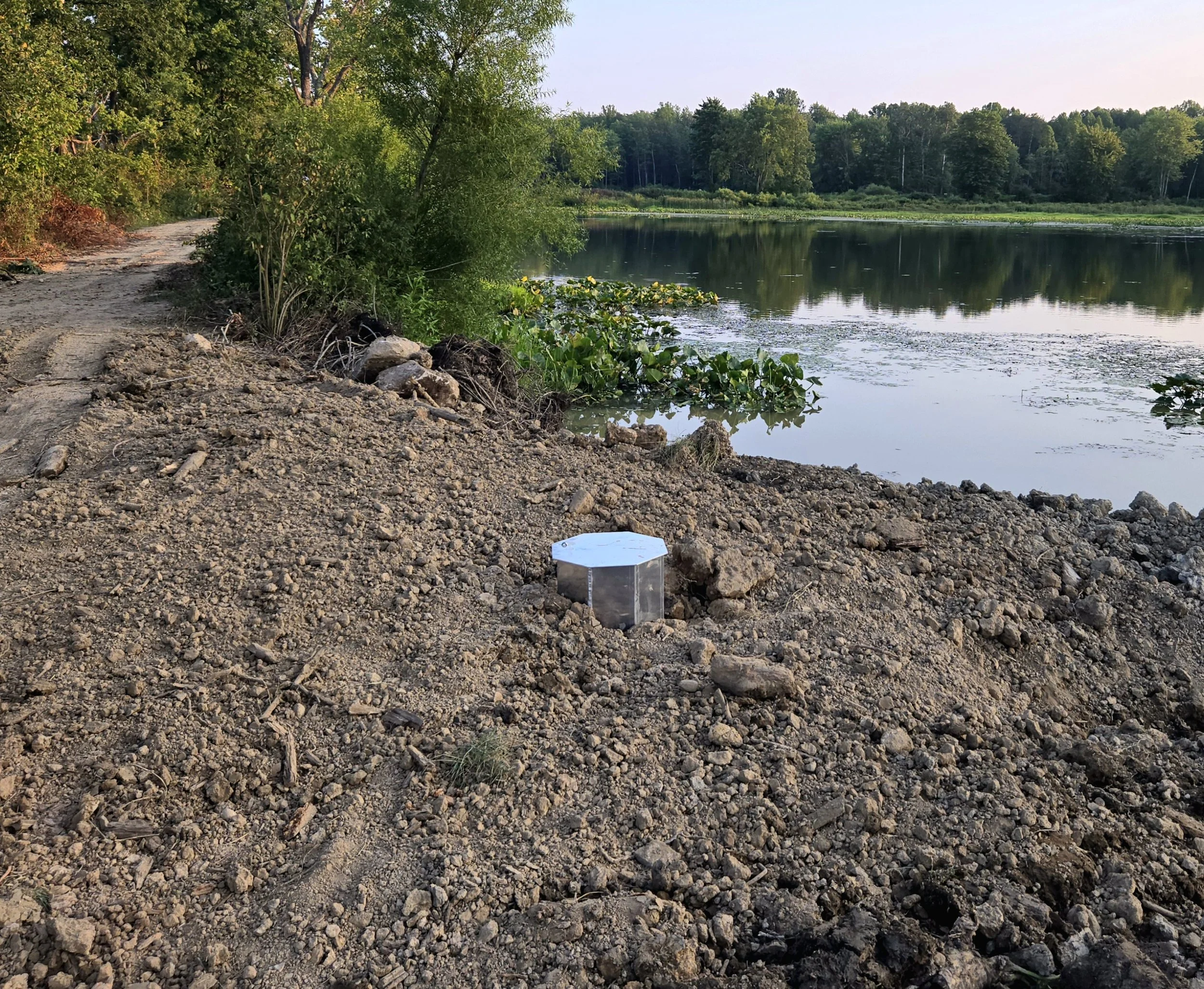
After backfilling was complete, the area around the box was graded.
The stoplogs and lid were put into place. We waited a few days to start the water flow to avoid pushing muddy water and sediment downstream.
Notice the box is placed to the side of the dam road and there is abundant space around the box for maintanence.