Setting Your Pond Leveler to Vary The Flow Height As Water Depth Changes
Variable Flow Rate Example
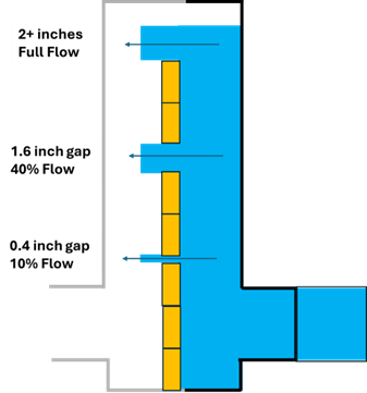
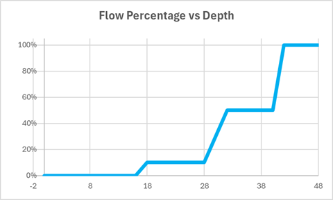
The level of a pond is regulated with a Drainbox 6-inch controller. The owner wants the drain to flow as fast as possible when the pond is full, reduce to half the flow as the pond level falls by 12 inches and further reduce to ten percent flow as the pond level falls by 24 inches.
100% flow above the maximum desired water level.
50% flow at 12 inches below the maximum water level
10% flow flow at 24 inches below the maximum water level.
The height of each stoplog panel is 6 inches
The inside width of the six-inch inline controller is 7 inches.
The cross-sectional area of a six-inch pipe is 28.3 square inches.
10% of of the 28.3 pipe area is 2.83 square inches. 2.83 square inches divided by 7 inches wide is 0.4 inches.
Open a 0.4 inch gap between the 4th and 5th stoplogs (24 inches) from the top.
50% of remaining flow - 10% additional flow = 40% 40% of 28.3 is 11.23 square inches. 11.23 divided by 7 is 1.6 inches.
Open a 1.6-inch gap between the 2nd and 3rd (12 inches) stoplogs from the top